 |
 |
|
|
|
|
|
Firearms Technical Trivia, April 2001:
|
|
|
3. ASSEMBLY PROCEDURES
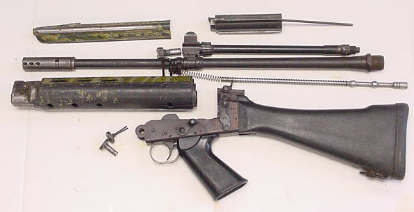
Congratulations, your FAL is now complete and ready for test firing.
It all starts with a dream. . . .
b. Hand Indexing the Barrel to the Receiver
Next, we hand fit the barrel to the upper receiver. We thoroughly cleaned both the barrel threads and the receiver threads with solvents and wire brushes, and then degreased both with acetone. When both were clean, we screwed the barrel into the receiver. The results achieved were as follows:R1 barrel/Imbel receiver: Barrel indexed to within 15 to 20 degrees of vertical
StG58 barrel/Entreprise Type 01 Receiver: Barrel indexed to within 15 degrees of vertical
R1 barrel/Entreprise Type 03 Receiver: Barrel indexed to within 20 degrees of verticalThese were exactly the results that were sought. The barrel should tighten to within 30 degrees (between 11 and 12 o'clock if you think of it using the clock scale) of proper vertical alignment if both the receiver and barrel threads have been properly cut.
There are, however, two error conditions that can obtain: When the barrel fails to come within a 30 degrees of vertical and when it hand tightens beyond the vertical (over tightens). There are many ways to compensate for either of these conditions, and we've noted the ones that worked for us - your mileage may vary.
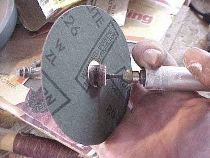
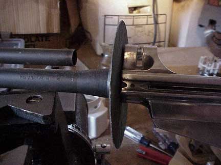
Under Tightening For the barrel that won't come within 30 degrees of vertical, the solution is to remove a little bit of metal from the barrel shoulder - the metal ledge at the very front of the barrel's threaded shank. Not a lot of metal, mind you, each additional degree of rotation requires a change of only about .00017" in the shoulder. The easiest and most sure way to do this is to obtain a few 80 grit sanding disks of the type for a 4" or 4.5" disk sander. Widen out the center hole until you can screw the disk onto the barrel threads with the abrasive facing the barrel shoulder, away from the revceiver, with a little bit of effort.Once screwed on, screw the receiver on behind the disk to give it some rigidity - the receiver should be tight enough to ensure that the disk can spin without a great deal of effort.
Courtesy of SameShot How far from proper indexing your barrel is will determine how many revolutions you need to spin the disk. Remember, you're only trying to get it to hand index to about 15 - 30 degrees. Be conservative, and back the disk off often so that you can check to see where the receiver indexes - you don't want to remove too much metal.
Courtesy of SameShot Over Tightening On the other end of the spectrum is the barrel that indexes too far, or over tightens. If this is the case you can either strike the outer edges of the shoulder with a brass hammer, causing the outer edges to swage outwards, or purchase some washers or steel shim stock. The washers will need to have an internal diameter of 1", and you'll want to sand, grind, or cut the piece so that the external diameter is equal to or less than that of the barrel shoulder. Carefully flat sand the washer or stock until the barrel comes to a stop between 15 and 30 degrees from the vertical. It is best to change the direction of sanding frequently and do both sides to keep the shim flat and parallel.
c. Barrel Installation
Installing the barrel is all in the setup, and there's no "approved" or right way to do it. We found that the following method worked for us, and again, your mileage may vary.The first thing we did was to very carefully mark the centerpoint of the barrel shoulder and the front of the receiver with a black magic marker. These marks were to serve as witness marks to aid in properly aligning the barrel and receiver. Next, we made sure that the handguard ring was properly positioned on the barrel. This is important as it's not a little frustrating to finish the perfect barrel job and look over to see that the handguard ring is sitting on your workbench. Next we clamped the barrel flats in the vise. When you do this, make sure that the jaws are shimmed with lead, aluminum or some other soft metal, so as to prevent marring of the barrel. We screwed the barrel onto the receiver hand tight, and affixed the receiver wrench.
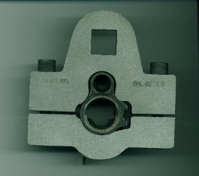
dramatically reduces the amount of effort needed to rotate the receiver, and allows for fine adjustments in the positioning of the barrel relative to the receiver.
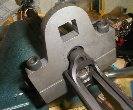
The Elliott Enterprises receiver wrench we used is a two piece affair that sandwiches the front end of the receiver between the upper and lower portions of the wrench. The two parts of the wrench are joined by a pair of 3/8" bolts with hex heads. The top of the wrench has a squared cut out that will accept a 3/4" breaker bar. Proper tightening of the wrench onto a receiver requires use of the appropriate size hex wrench. Problem is, a 3/4" breaker bar is an expensive item, costing nearly $50.00 at Sears. Instead, we opted to use a 1/2" breaker bar (less than $27.00) and a 3/4" adapter ($12.99). We also slipped a four foot length of steel pipe over the breaker bar to gain additional leverage. The use of such a "cheater pipe"
After all that, the actual torquing was anti climactic. Watching the witness marks carefully while pulling on the cheater pipe, it took us all of about forty-five seconds to position the barrel. After removing the wrench from the receiver and the barrel from the vise, you can verify the proper alignment by installing the gas cylinder and gas cylinder bushing/rear support. Without the carrying handle installed, it should screw into receiver easily and without binding. Then insert the gas piston and insure it moves freely. Visually inspect the alignment once more. Unfortunately, the ultimate test for proper alignment is to fire the rifle. If the groups refuse to center no matter how far over the rear sight is pushed, this is an indication that a re-alignment is in order.
d. Setting the Headspace
Headspace is the distance from the breech face to some datum point on or in the chamber or barrel. For a complete discussion of what headspace is, and how to measure it, see the article entitled "A Headspace Primer," in the October, 1999 issue of CRUFFLER.COM. With reference to the FAL, the headspace dimension is that distance from the bolt face to the portion of the chamber where the internal diameter is exactly 0.400". As with many mechanical assemblies, this distance is expressed as a tolerance, rather than an absolute. According to FN, the headspace tolerance for an FAL is:
FN Factory Headspace Dimensions Minimum 1.6315" Maximum 1.640 Unfortunately, it gets a little more complex. In addition to the absolute maximum, FN also specified a maximum for a new or overhauled rifle of 1.638". That is to say, there are two maximum headspace dimensions, one for a factory new or overhauled rifle and one for a rifle that has been in service. This is shown more clearly below:
FN Factory Headspace Dimensions, New and In-Service Rifles Minimum 1.6315" Maximum, New Rifle 1.638" Maximum, In-Service Rifle 1.640" The equation becomes more difficult when one takes the SAAMI headspace specifications for the .308 Winchester into account. While the 7.62mm NATO and the .308 Winchester are not the same cartridges, and should by no means be considered interchangeable, they are often used synonymously in the United States, and because of their dimensional similarities, only gauges and reamers for the .308 Winchester exist. The SAAMI specification for .308 Winchester headspace dimensions are noted below:
SAAMI Headspace Dimensions, .308 Winchester Minimum (GO) 1.630" Maximum (FIELD) 1.640 You'll note that there is no "NO-GO" specification. SAAMI doesn't specify one. The NO-GO specifcation, measurement, and gauge are products of the gauge makers, and can be whatever the manufacturer decides it should be (within the bounds of the minimum and maximum dimensions). This is why the Forster .308 Winchester No-Go Gauge measures out at 1.634", while the Clymer .308 Winchester No-Go Gauge measures out at 1.636". However Forster's Field gauge measures out at 1.638", inidicating that Forster builds a .002" margin into its gauges that is not the same as the SAAMI specified .308 Winchester maximum headspace dimension. For this reason, we opted to go with the Clymer gauges. Taking all this into account, the consolidated headspace dimensions look like this:
Consolidated FN Factory and SAAMI Headspace Dimensions, New and In-Service Rifles Minimum, SAAMI 1.630" Minimum, FN 1.6315" Maximum, FN New Rifle 1.638" Maximum, FN In-Service Rifle and SAAMI 1.640" Optimal assembled FAL headspace range then, is: 1.6315" < Rifle Headspace < 1.638".
As you can see, it is possible to build a rifle with a chamber within SAAMI specification for .308 Winchester, but undersized for the FAL. Since we weren't building a match rifle, but rather a military style self-loader, we opted for fairly generous headspace dimensions so as to ensure compatibility with as wide a range of surplus 7.62mm NATO ammunition as practicable. Consequently, we decided to use the Clymer 1.636" NO-GO gauge as our headspace benchmark.
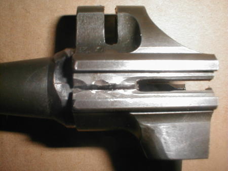
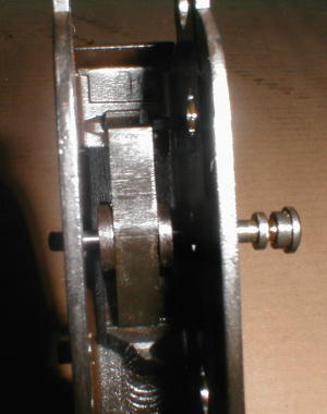
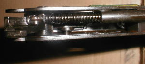
Setting headspace with the use of Elliott Enterprises Locking Shoulder Sizing Rods is surprisingly simple. The rods themselves are basically a pair of stepped cylinders that are precision machined for diameters each ranging from .2454" to .2766". One first diassembles the bolt using the extractor tool, and then thoroughly cleans and degreases both the bolt and the chamber. Dirt or foreign matter can cause erroneous or misleading headspace readings. We used the vise to hold the receiver, muzzle tilted downward, shimmed between two blocks of wood.
The stripped bolt was assembled into the bolt carrier, the Clymer NO-GO Gauge inserted into the chamber, and the smallest diameter section (.2454") of the smaller of the two rods inserted into the locking shoulder hole in the receiver. The rod was held against the rear edge of the locking shoulder recess and the bolt - carrier assembly permitted to ride home. If the bolt closed, the process was repeated with the next larger section of the rod. The iterations continue until the bolt will not close under "two thumb pressure" (that scientific term comes from the Canadian armorers manual for the C1A1). You now know the smallest size of locking shoulder that you'll need.
At that point, the NO-GO gauge is removed and the GO gauge inserted into the chamber. Using the same section of rod in the locking shoulder recess, the bolt was again allowed to ride home. It should (and did) close readily. Keep placing larger diameter sections of the gauge in place and trying to cloe the bolt. When you find where the bolt will not close, back off one size and retest. This is the largest size shoulder you can use relative to the smaller size that would not close on the NO-GO gauge. From this you can determine a range of locking shoulder sizes that wil yield positive results. If the locking shoulder that came with your kit is within thiw range, you're in business. From this, we were able to determine that the .257" locking shoulder supplied with the kit was eminently serviceable.
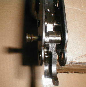
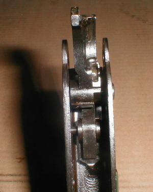
above the punch was sufficient to generate enough force to seat the locking shoulder.
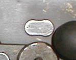
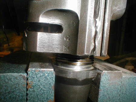
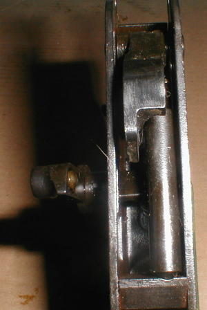
Seated Locking ShoulderOnce we selected the proper locking shoulder, the receiver was laid on its left side on a section of railroad tie. The oblong end of locking shoulder was carefully lined up with the corresponding receiver recess and started with a few taps of a hammer. Once started, the locking shoulder was driven home using a 3/8" pin punch and healthy hammer blows. Interestingly, the amount of effort needed to drive the was not extreme; bringing the hammer four or five inches 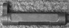
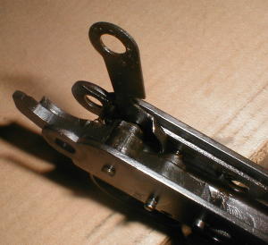
Uninstalled
Locking ShoulderImage Credit:
Arizona Response Systems
ARS publishes an excellent FAL Workbook by owner
T. Mark GrahamOnce the locking shoulder was fully seated, we repeated the headspace gauging, ensuring that the bolt would close on the GO gauge and not on the NO-GO or Field Gauges.
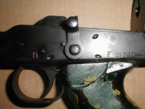
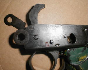
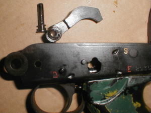
e. Fire Control Assembly
In order to keep the rifle in compliance with various firearms laws, a number of perfectly good parts must be replaced by domestically manufactured parts. Among those pieces typically replaced are the fire control components, including the trigger, hammer and sear. This means that the existing fire control parts will have to be removed, and the domestic parts installed in their place. We used both DS Arms and Entreprise Arms fire control parts. Disassembly of the fire control assembly is much simpler than it appears, but is very dependent on the proper sequence. The lower receiver should be disassembled from the upper.1. Cock the hammer.Before reassembling with the new components, the new trigger and sear must be assembled with a slave pin. The two share a common pin, and are under spring tension, so without the slave pin, it will be difficult if not impossible to hold the two in position. We found that a 5/32" roll pin cut to size worked perfectly. You may also need to use a nylon headed hammer or a nylon punch to reassemble the trigger pin into the receiver. Otherwise reassembly is straightforward:
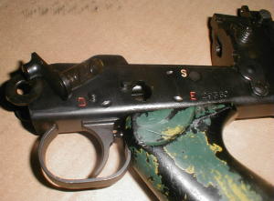
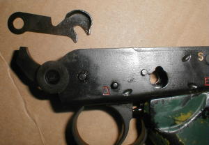
2. Rotate the selector to the vertical position and pull it out to the left. 3. Release the hammer - it will rotate further than normal as the spring steel clip that limits rotation is no longer held in place by the selector.
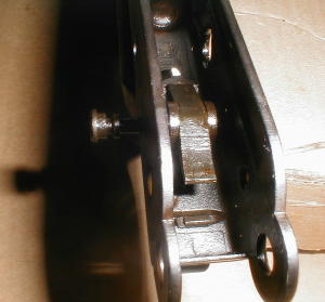
4. Gently pop the rear end of the hammer spring upwards and out of its seat in the hammer with a screwdriver or other such tool.
5. Rotate the spring steel retaining clip on the right side 180 degrees and ease it up off the hammer pin.
6. Using a brass or other non-marring drift, tap the hammer pin out from left to right, and remove the hammer.
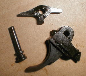
7. Using a brass or other non-marring drift, tap the trigger/sear pin out from left to right, and remove the trigger and sear.
1. Seat domestic trigger/sear assembly with slave pin inside the lower receiver.
2. Tap the trigger pin into place from right to left, displacing the slave pin.
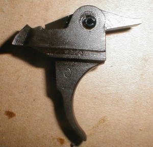
3. Position the domstic hammer and tap the hammer pin into place from right to left.
4. Slip the retaining clip over the hammer pin and rotate it 180 degrees to the rear.
5. Reseat the hammer spring assembly.
6. Cock the hammer. 7. Reseat the selector.
f. Gas System Installation
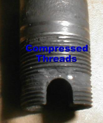
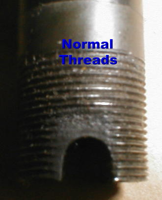
Inspect your components! This cannot be overstressed. When fully assembled, the gas tube's rotation in the gas block is arrested by a small pin driven through a hole in the gas block. This pin is only visible if the gas adjustment ring is almost completely unscrewed from the gas block. With
worn appearance. This adversely affects function in the following ways:
the pin removed, the threaded portion of the gas tube readily screws into and out of the gas block. When the pin is installed, the gas tube requires a great deal of effort to turn. Unfortunately, many rifles have had the gas tube forcibly removed with the pin in place by those unaware of its presence. The result is that the threads at the front of the gas tube are compressed leading to a stepped,
If you see evidence of this "gas tube abuse," your best bet is to order a new gas tube.
- The gas tube is no longer held firmly in place by the pin, and may rotate. This can cause the gas port to close regardless of the gas adjustment ring setting.
- The gas piston may bind in the tube, which may have been slightly narrowed at the front.
- The gas tube may no longer provide an effective seal in the gas block resulting in gas blow by and failures to function.
A second point of inspection is to make sure that the gas tube retaining pin is included with your kit. If not, don't worry. A 1/2" length of 5/64" roll pin works just fine as a replacement.
Our first step was to screw the gas adjustment ring onto the gas block. This part goes on with the stepped edge of the ring forward. Next the gas adjustment ring spring (the small U-shaped piece of wire with bent-in tips) was muscled into position. Note that there are two small troughs on the sides of the gas block for the spring's arms, and two small holes for the tips. Then we backed the gas ring off until the gas tube retaining pin hole was visible on both sides of the gas block.
The gas tube, with the rear bushing/support was then screwed into the gas block as far as it would go, and the rear bushing/support into the receiver. (Note that the ease or lack thereof of screwing the rear bushing into the receiver is an indication of how well the barrel and receiver are indexed.) The gas piston, spring, and plug were then installed.
Next, we looked down at the gas port and slowly unscrewed the gas tube until we could see the silver gas piston completely filling the port (1/8 to 1/2 turn). While holding the tube in this position, the gas tube retaining pin was gently tapped into place and seated with a pin punch.
Finally, the gas adjustment ring was screwed all the way on, and then backed up to the fully "open" position to insure that the gas tube retaining pin wasn't binding.
g. Cocking Handle Installation
Cocking handle installation was relatively simple and straightforward. Indeed, it only gets difficult when one tries to install an inch pattern folding cocking handle on a metric upper receiver. We opted to use the metric pattern cocking handles that came with the kits.1. Slip the cocking handle knob and slide into the groove on the left side of the upper receiver. The cocking knob should be positioned toward the front (barrel) end of the receiver.2. Pull the handle about midway to the rear.
3. Insert the cocking lug into the recess on the cocking handle slide. Looking down from above, you should be able to see daylight through the corresponding retaining pin holes in the cocking handle slide and the groove in the cocking lug.
4. Using a pin punch, drive the cocking lug retaining pin through the hole so that it is flush with the top of the cocking slide.
h. Muzzle Device Installation
The muzzle device is, like the fire control assembly, another place where Congress has created additional work for the intrepid FAL-builder. One may not have a threaded muzzle on a firearm with a separate pistol grip that is classified as a "semiautomatic assault weapon." (An oversimplification, we know!) Consequently, there are two ways to go - one can remove the threaded portion of the barrel or one can permanently attach a device that covers the threaded portion of the barrel. Permanent attachment is a tricky subject in and of itself, but there are two realistic options: Blind pinning a muzzle device in place or brazing/soldering with a soldering agent that has a minimum melting temperature of 1,100 degrees Fahrenheit. Since soldering is much simpler, and requires a lot less in the way of tooling, we went with that approach.In addition to threaded muzzles, the legislatively defined "assault weapon" may not have any of the following evil features:
Since the short Belgian muzzle device that comes with most kits fulfills all three of these roles, it must be replaced or physically altered. As an added incentive, the muzzle device counts toward the required quotient of domstically produced parts. Entreprise Arms, DS Arms, and John Glover all manufacture alternative muzzle devices that are of high quality.
- Bayonet Lug
- Grenade Launcher
- Flash Suppressor
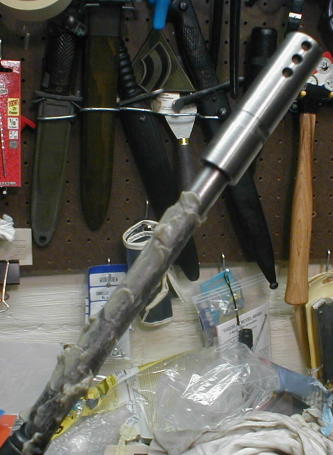
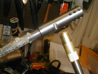
The first step in soldering your muzzle device in place is to thoroughly clean and degrease both the brake and the areas of the barrel to be soldered. We cleaned with solvent and a wire brush until the areas in question were bright and shiny. After several iterations, we degreased both the barrel and the brake with acetone and set them aside to dry (not a very long wait - acetone evaporates very quickly).
Next, we applied Brownells' Fusion (STL 1205) Silver Solder and Flux Paste to the threads. While the paste is more expensive than using traditional silver solder and flux, it's much easier to use, and the once ounce container will suffice for 10 - 15 applications. We applied the paste with a small flathead screwdriver tip, carefully pressing into the barrel threads. Once the paste was applied, we carefully screwed on the muzzle device of choice (the R1 barrel in the photograph received one of John Glover's Belgian Short Brake lookalikes) until it was fully seated, and then completely unscrewed it. This distributed the silver solder paste around the barrel and brake threads.
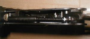
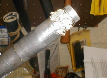
You're going to get the brake and the relevant portions of the barrel very, very hot. In general it's not recommended to heat the barrel to extremes, so we recommend that steps be taken to minimize the effects of the heating on the barrel. We opted to use Brownells heat stop paste. This paste absorbs the heat trasmitted down the metal and helps to prevent heating of any portion of the barrel other than that which you are specifically trying to heat. The paste was liberally slathered on the barrel, from the gas block to about one inch below the bottom of the muzzle device. Note the bright silver color of the muzzle device in this photo.
Now it's time to fire up that MAPP torch and get to it. It's important to use either a MAPP torch or an oxy-acetylene torch as regular propane torches simply don't get hot enough fast enough. MAPP torches are available in your local home center at about $40.00. After indexing the muzzle device, ignite the torch and play the it over the threaded portion of the device. It's important to keep the torch moving and to heat all portions of the device evenly so as to melt all the flux and solder. When you see the device glowing a dull red, stop heating. Immediately apply a wet cloth to the section of the barrel treated with heat stop paste. After about a minute apply a wet cloth to the brake. This will help cool the parts down more rapidly and help to minimize the effects of the heating on the heat treatment of the metal.
i. Final Assembly
Final assembly included mating the upper and lower receivers and affixing all the small parts not previously assembled:1. Invert the lower receiver and drop the bolt hold open device into the slot. It only fits one way.2. Slip the magazine catch and spring into their recesses in the upper receiver.
3. Use a drift or other suitable slave to compress the hold open device spring.
4. Slide the magazine catch pivot pin/hold open retaining pin into the upper receiver. It should go through the magazine catch and hold open. Tighten it with a screwdriver.
5. Cock the hammer in the lower receiver.
6. Slip the upper receiver pivot point into the lower receiver and close the two as though closing an assembled rifle so that they are held together by the take down latch.
7. Slip the hollow, non-slotted half of the take down pin into the receiver pivot point from right to left.
8. Slip the slotted, split rod half of the take down pin into the hollow half and tighten it down with a screwdriver.
9. Break open the action and slide the assembled bolt/carrier into place, and then slide the dust cover into place. Close the action.
10. Push the upper sling swivel loop over the collared portion of the barrel, and then secure the sling swivel with the sling swivel screw.
11. Remove original pistol grip by unscrewing the retaining nut and pulling it down and off the post. Replace with domestically manufactured part.
12. Buttstock removal is achieved by removal of the screw at front underside of buttstock, followed by removal of the buttplate/buttpad screw and buttplate/buttpad. Using the specialized buttstock tool, unscrew and remove the recoil spring plug. The recoil spring will come with it, so be prepared! Pull the butt off the recoil spring tube to the rear. Replace with domestically manufactured part (if desired).
13. Install handguards.