CRUFFLER.COM
presents
HISTORIC
FIREARM OF THE MONTH,
September
2001:
|
|
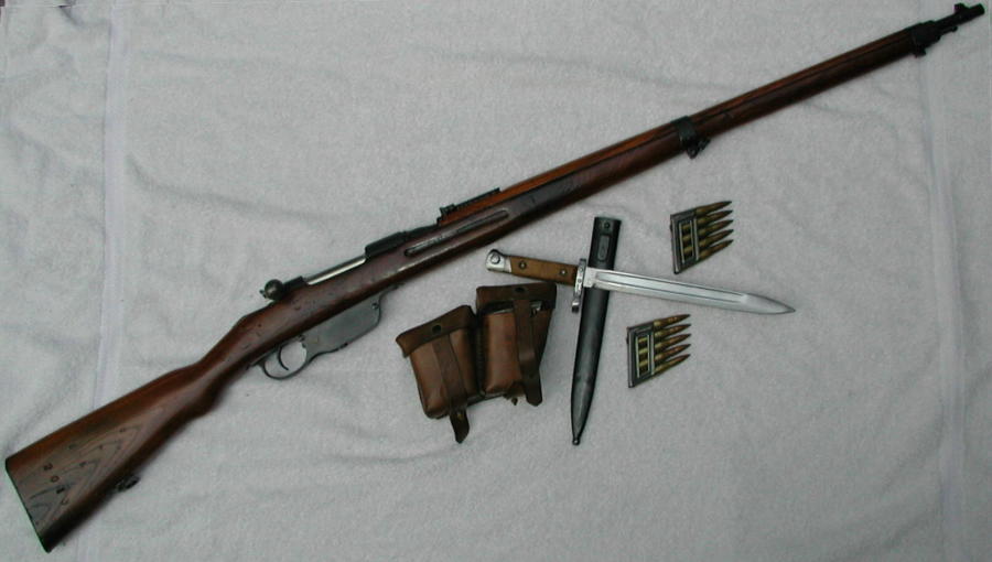
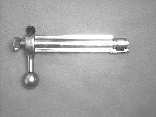
The Mannlicher
Model 95 Straight Pull Magazine Rifle |
|
|
|
Type:
Straight Pull Bolt Action Rifle
System
of Operation: Manual
Caliber:
8x50mmR (later 8x56mmR)
Capacity:
5 round en-bloc clip
Sights,
front: Drift Adjustable Blade
Sights,
rear: V-notch on ladder, adjustable
from 300 - 2600 schritt or 500 - 2000 meters
Length:
50"
Weight
(unloaded): 8.9 lbs
Barrel:
30.12", 4 grooves, right hand twist, 1 turn in 9.842"
|
HISTORY
AND MECHANISM
The Mannlicher
Model 1895 Infantry Rifle was initially adopted in 1895 by Austria, Bulgaria,
and Greece, and was the standard Austrian service arm during World War
One. Huge number of Model 95's were surrendered to the Italians as
part of the peace treaty that ended Hapsburg participation in that conflict.
These rifles surfaced again in the hands of Italian troops during World
War Two, and were also used by Austrian formations within the Wehrmacht
as well as by government and resistance forces wherever Austro-Hungarian
influence had been prevalent.
The most widely
used and well known of Mannlicher's rifle designs, the Model 95 evolved
from the earlier Model 90 carbine, and shares the same fundamental design
characteristics. There were minor mechanical improvements, however,
most notably in the shape of the striker nut, and of course those involved
in converting the earlier design from that of a carbine to a rifle.
The rifle was designed to use the standard 8x50mmR Austrian Army cartridge.
Due to the development of new metallurgy at the Steyr factory during the
rifle's development, the Model 95 used a
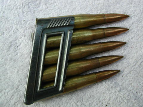 M31 8x56mmR
ammunition in en bloc clip
|
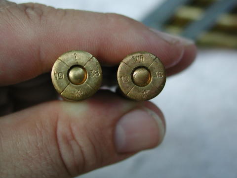
M31 8x56mmR ammunition headstamps
before (left) and after (right)
the Anschluss
|
much lighter and
thinner barrel than previous smokeless powder designs. By shortening
the receiver and the magazine and using a revolving bolt head locking mechanism,
the designers were able to reduce the Model 95's weight by about 1.75 pounds
from previous Austrian service rifles. Originally chambered for the
8x50mmR Austro-Hungarian service cartridge, many Model 95's were rechambered
for the improved and more powerful 8x56mmR M31 cartridge in the 1930's.
This rechambering gave the Model 95 and its carbine and short rifle variants
accuracy and striking power comparable to any other contemporary infantry
rifle.
The Design
and Components
The heart
of the rifle, the receiver, is milled out to the rear of the barrel, which
is screwed and torqued into it, to form the locking lug recesses.
There is a long slot cut in the receiver's tang for the sear and ejector,
while further to the rear, a transverse slot is milled so that the trigger
horns can project through it. The receiver tang is also grooved to
accept the cocking piece guide stud, and on either side of this groove
there is an undercut groove in which the feathered portions of the bolt
slide so as to provide rotation during the straight pull and push motion
of the bolt handle.
|
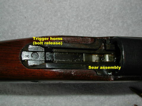
M95 Receiver Tang
|
The
rearward motion of the bolt is arrested when the feathered portions contact
projecting horns on the trigger; this also serves to prevent the bolt from
being inadvertently removed from the receiver during rearward motion.
(Pulling the trigger forward will permit easy removal of the bolt.)
A groove on the right side of the receiver is slightly cut away to permit
the empty case to be ejected and to enable the magazine to be rapidly loaded. |
The barrel
has a noticeable taper, diminishing in diameter from the chamber end towards
the muzzle and is screwed into the receiver with a standard right hand
thread. The front sight block is part of a sleeve affixed to the
barrel by means of a
| cross-pin.
The front sight itself is of barleycorn design which is dovetailed into
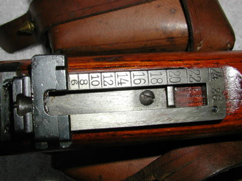
the sight block perpendicular to the axis of the barrel. The rear
sight bed fits around the barrel and is secured to the barrel by means
of a crosspin. The rear sight itself has two components. When
folded, a fixed V-notch battlesight, graduated to 500 schritt (paces)
is presented to the shooter. When the rear sight leaf is raised,
an adjustable V-notch graduated by hundreds for ranges between 600 and
2,600 schritt is presented. |
M95 Rear Sight
|
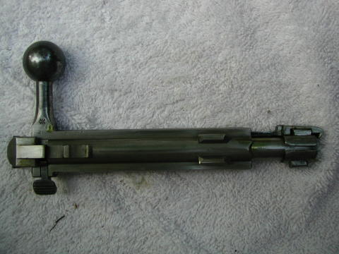
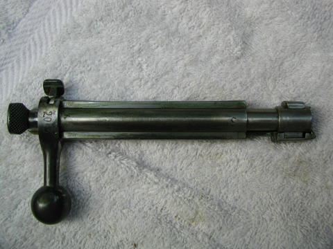
The Straight
Pull Bolt
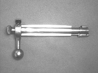
The bolt proper
consists of the hollow bolt body with the bolt head inserted from the front.
The rear portion of the bolt body is heavily reinforced and carries the
horizontally projecting bolt handle. On either side of the bolt body
are ribs that move in corresponding raceways in the receiver. At
the lower forward edge are two projections that produce the revolution
required to lock and unlock the action. At the rear of the bolt is
a small safety projection with a groove in it for the ejector to rest on
when the bolt is closed.
|
M95 Bolt Bottom. Note Czech
acceptance stamp on bolt root
|
M95 Bolt Top
|
The rear portion
of the reinforced area of the bolt is milled out to receive the nose of
the cocking piece. The cocking piece is separated in the bolt from
the bolt head by a collar secured by a screw. A point on this collar
projects into the firing pin hole where it bears against a flat on the
firing pin to prevent the firing pin's rotation. The center section
of the bolt cylinder has two helical cams on the inner surfaces that work
on corresponding grooves in the tail of the bolt head. There is also an
internal groove to receive the extractor, and the locking and safety bolt
is positioned on the left side of the bolt cylinder reinforce.
The bolt head
is composed of the head itself, which projects beyond the face of the bolt
body and a tail which enters the hollow body. Two cam shaped locking
lugs are machined into the the head of the bolt. These enter their
recesses in the receiver after passing along the cam shaped travel grooves
and hold the bolt head firmly against the cartridge head when locked.
The bolt head has a groove milled into it for the ejector, as well as helical
grooves in which the bolt body cams ride. Each of the helical grooves
has a small groove leading out in the direction of the length of the bolt,
forward and rear.
The striker
spring (which is coiled to a length of about five inches) and the striker
within it are housed in the bolt head. The rear end of the tail of
the bolt head is closed by a screw plug against which the striker spring
bears at the rear while the striker passes through the plug hole.
The front end of the mainspring bears against a collar on the striker.
The Extractor
The Model
95's extractor is a long, flat spring housed in the right rib of the bolt
cylinder. The front end fits over the right locking lug and ends
in a broad hook that grasps the rim of the cartridge case. The rear
end has a small nib on the underside engaging in the longitudinal grooves
in the tail of the bolt head. When the breech is closed, this nib
engages in the longitudinal groove at the top of the bolt head tail, but
when the bolt is pulled to the rear, the nib rises out of the groove, and
when the bolt makes a ninety degree turn to the left, it seats in the opposite
groove. At this point the right lug is under the extractor head and
the extractor is pulled to the rear by the bolt.
The Model 95
extractor is of the controlled feed type where the extractor snaps over
the rim of the top cartridge in the magazine while the bolt is advancing
to push the cartridge into the chamber. Since the cartridge is thus
held securely during all forward and backward motions of the bolt, save
at time of ejection it makes it impossible to "double load" and jam the
rifle.
Fire Control
Mechanism
The cocking
piece which works in the rear end of the bolt body screws on to the end
of the striker. It has a groove in the left side into which the safety
locking bolt can engage when it is used to lock the action. The safety
can only be engaged when the action is cocked. When the striker is
at full cock and the locking bolt thumb piece is turned, the locking bolt
is thrust between the front face of the cocking piece and the rear face
of the bolt cylinder. The tip of the lock is cam shaped, and as a
result, when thrust into position it forces the cocking stud back out of
engagement with the sear to prevent the rifle from being fired accidentally,
and pulling the trigger will not discharge the rifle. The locking
bolt is fastened to the reinforced area of the bolt cylinder by a screw,
a system adapted from the Mannlicher Models 1888 and 1890.
The ejector
is pivoted to the front of the sear body, with the lower end forced forward
by the action of a small spiral spring and its upper end pressing the sear
and the sear nose backward. The upper end of the ejector is somewhat
depressed by the bolt, and the spring therefore partially compressed, thus
providing tension to enable the sear and sear nose to function. The
sear has two parts, a body and a nose pivoted on the same pin which passes
through the receiver. The sear nose fits into a slot cut into the
receiver. The trigger is a bell crank lever whose long arm projects
downward through the trigger guard as a finger piece while the short arm
terminates in a hook which engages the rear of the sear. The cross
piece has two arms that project into the path of the bolt so as to prevent
inadvertent withdrawal is set at an angle. The trigger is not pivoted
to the receiver, but supported in its groove in the receiver by the sear.
Firing Sequence
When the bolt
is drawn to the rear, it moves only in a straight line and cannot revolve
due to the ribs on its underside moving within the corresponding linear
grooves in the receiver, and the cocking piece moving within the tang groove.
As the bolt is drawn to the rear the bolt head cannot begin rearward movement
until the locking lugs have been turned out of engagement with the locking
lug recesses in the receiver. The necessary rotation is effected
by the twisting motion given to the tail of the bolt head by the helical
projections on the inside of the bolt body working on the grooves on the
bolt head tail.
Primary extraction
is effected by the cam shape of the locking lug recesses. At the
same time, the first movement of the bolt to the rear partly compresses
the striker spring. The turning bolt lugs assist in the rearward
motion of the bolt. Cartridges are stored in an en bloc clip within
the triggerguard/magazine and forced upward by a spring loaded follower.
The bottom rear of the magazine is open to permit the empty clip to fall
out when the last round is chambered. Interestingly the Mannlicher
clip is a "one way" device that can only be inserted if held in the proper
vertical orientation. The front of the magazine bottom is closed
by a trough piece secured by a screw. The magazine follower is pivoted
at the front end of this trough and is actuated by a strong flat spring
attached by a screw to the rear end of the trough. As the loaded
clip is inserted from above, the bottom cartridge depresses the follower.
During operation of the rifle, the spring thrusts the cartridges up.
A clip release is provided; when the action is open, pressing the catch
at the forward end of the triggerguard will withdraw the locking hook at
its upper end from engagement with the clip and permit the follower to
drive the loaded or partly loaded clip out of the top of the action.
When the bolt
head has rotated far enough to disengage the lugs from the recesses, the
lugs are then in line with the ribs on the bolt body. From that point
onward, the entire bolt assembly moves directly to the rear. Rearward
motion is halted when the feathers on the underside of the bolt strike
the horns projecting from the trigger into the receiver. The cartridge
case being extracted is held firmly by the extractor until it strikes the
ejector and is hurled from the rifle.
Forward motion
of the bolt handle reverses the sequence. The sear nose catches the
stud of the cocking piece to complete compression of the striker spring.
The bolt studs force the bolt head to twist into the locked position as
a cartridge is driven into the chamber.
Squeezing the
trigger lowers the nose of the sear to release the cocking stud and permit
the striker to move forward under pressure from the spring. The front
of the sear body is then elevated into the boltway behind the safety projection
at the rear end of the underside of the bolt, positively preventing any
rearward movement when the rifle is being fired. Additionally, when
the bolt is slid forward, the safety projection slides over the forward
edge of the sear to prevent it from rising, thus preventing accidental
firing and insuring that the rifle cannot be fired until the head is fully
forward and the lugs locked into their recesses. In the event of
a misfire, the striker can be manually cocked without having to open the
bolt and the shot retaken.
ERGONOMICS
AND SHOOTING
Despite its
length, the Model 95 rifle feels surprisingly light. This is due
to the long, thin barrel and the use of a comparatively thin stock and
fore-end, which distribute the rifle's weight quite evenly along its length.
Well balance, the M95 comes easily to the shoulder and has a natural pointability
akin to that of the Tokarev SVT-40, the M1 Garand and the Dragunov SVD.
For those used
to Mauser or Enfield bolts, the straight pull action feels jerky and rough
at first. Indeed, we found it almost impossible to operate the rifle
without powering the bolt back and forth. While the action
may not be ideal for snipers or other employment where the need for stealth
is paramount, it is one of the fastest bolt actions we've ever tried.
On the range we were able to fire thirteen rounds to the Mauser's five
and the Enfield's eight during a speed test, a feat more impressive given
that the Mannlicher had the most stout recoil of the three.
Speaking of
recoil. . . the Model 95 we tested was chambered for the 8x56mmR cartridge.
This round pumps a 208 grain bullet downrange at approximately 2,350 feet
per second, which puts it right in the ball park with the .303 British
(174 grains, 2,440 fps) and 7.92x57mm Mauser sS (198 grains, 2,500 fps).
Despite these ballistic similarities, the Model 95 easily had the heaviest
recoil when compared to a No. 1 Mk. III* Enfield and a Gewehr 98.
Not enough to be painful, but definitely enough to make even the most recoil
inured shooter stand up and take notice.
The big "if"
for the casual shooter in terms of accuracy with a Model 95 is sight in.
The sights really ARE graduated for 500 paces, and shooting at a 100 yard
target can leave the shooter frustrated and perplexed as to why there aren't
any impacts on the target. We affixed a 2" orange dot to a sheet
of newsprint and were able to see groupings that struck about seven inches
above the point of aim. Average groups using 1938 surplus ammunition
were about 2.9". Our best group was a cloverleaf of about 1.1".
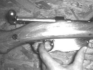
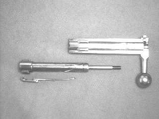
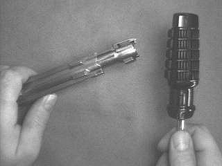
FIELD STRIPPING
Bolt removal
is easy - just push the trigger forward and pull the bolt out. Bolt
disassembly is a bit more . . . challenging and should not be attempted
without a very cogent set of instructions, lest . We've reprinted
Cody
Wykert's excellent article on stripping the Model 95 bolt below:
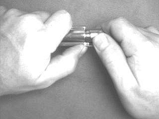
Disassembly
For
Assembly Info Click Here
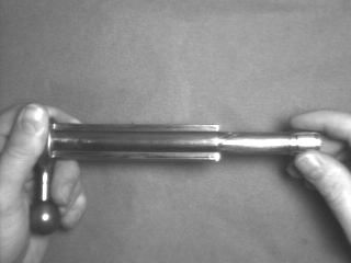
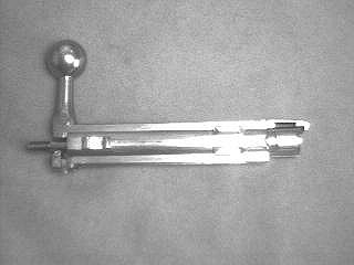
| Step
1 - Remove the bolt |
| Put
the safety lever in the "fire" position and pull the bolt as far back as
it will go. Perform standard safety checks here, making sure the
rifle is unloaded, etc.. Now push the trigger forward, hold it there,
and quickly pull the bolt backwards out of the receiver. If it doesn't
come completely out, the bolt head is trying to rotate and is slightly
binding under spring pressure. Wiggle the bolt around while pulling
it back and keep the trigger pressed forward. It should eventually
slide out. |
Push the
trigger forward to remove the bolt.
|
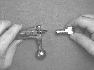
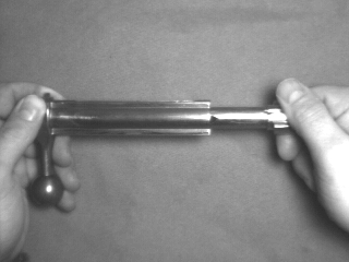
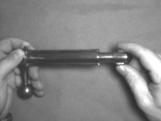
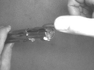
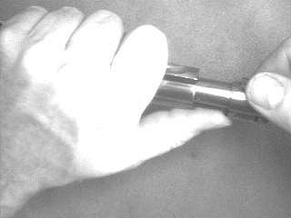
| Step
2 - Rotate the bolt head |
| The
bolt head may, or may not retract inward from spring pressure when the
bolt is removed from the receiver. If it does not, you will need
to tap on it with a soft-faced hammer. I use the rubber coated handle
of my $10 Kmart driver. Try to avoid hitting the extractor.
You want the bolt head to be retracted inward for disassembly. |
Bolt head
in outward position.
|
|
Bolt head
being tapped.
|
Bolt head
retracted inward.
|
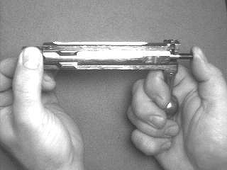
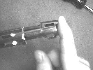
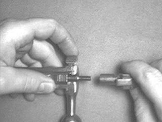
| Step
3 - Unscrew the cocking piece |
| Hold
the bolt so you can manipulate the safety lever with your index finger.
Hold the safety lever halfway between "safe" and "fire" positions.
With your other hand, grab the cocking piece and pull it back. Now
move the safety lever into the "safe" position and hold it there while
unscrewing the cocking piece. After about 8 revolutions, you can
lift the safety lever slightly and let the cocking piece retract back into
the bolt body. This makes the last few turns easier. |
Hold the
safety lever at halfway position.
|
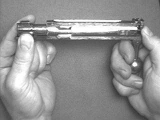
|
Pull cocking
piece back (heavy spring pressure).
|
Hold safety
lever in the "safe" position while unscrewing cocking piece (counter-clockwise).
|
|
Cocking
piece removed.
|
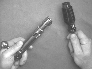
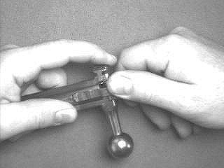
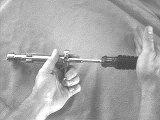
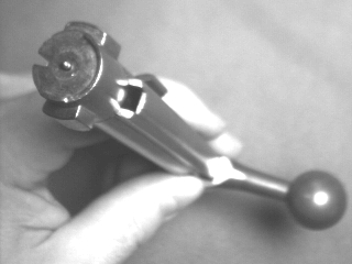
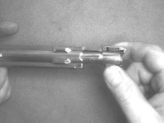
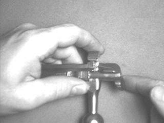
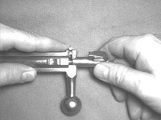
| Step
4 - Remove the bolt head assembly and extractor |
| Grasp
the bolt as shown below. Rotate the head 90 degrees clock-wise and
push the assembly out with your thumb at the same time, until it "clicks".
At this point you can pull the head assembly out with brute force, or very
carefully tap it out from the back, being conscientious of the
threads. |
Hold the
bolt like this.
|
|
Turn the
bolt head clockwise while pushing the assembly out with your thumb.
|
Kmart
wonder driver to the rescue. The hollow tip fits perfectly over the
rear of the firing pin shaft. A rap on the drive handle pushes
the entire assembly out.
|
|
Bolt head assembly
and extractor separated from bolt body.
|
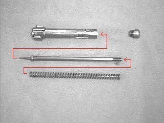
| Step
5 - Take down the bolt head assembly |
WARNING
- FLYING PARTS HAZARD!
The spring inside this
assembly in under a lot of tension. Hang on tight!
Unscrew the retainer as
shown below. |
Unscrewing
the retainer.
|
|
Components
of the bolt head assembly.
|
| Miscellaneous
Info |
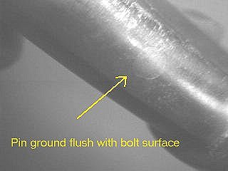
| At
this point the bolt is
almost completely taken down. There
are two part that I don't mess with. If you look inside the bolt
body (breech side), you can see a bushing that the firing pin shaft passes
through. I can't see a reason for removing it unless it's damaged.
Besides, it's appears to have a pin passing through it that's been ground
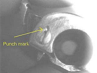
flush with the outer bolt surface. Also, the screw holding the safety
lever in place has been punched. It's not coming out without being
drilled. |
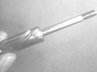
Slots
in the bushing.
|
|
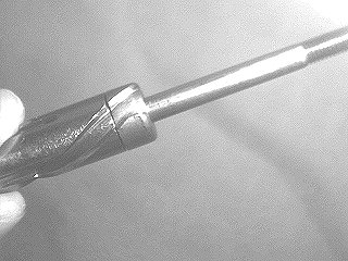
Pin holding
bushing in place.
|
Screw
holding safety lever in place
|
Assembly
| Step
1 - Put the bolt head assembly back together |
| Undo
everything you did in step 5 above. When the retainer is fully screwed
into place, it's grooves will probably NOT align with those on the bolt
head's shaft. This is ok. Just unscrew it until the grooves
line up. |
Retainer
tightened completely down. Grooves are not aligned.
|
|
Unscrew
retainer until it's grooves line up with those on the bolt.
|
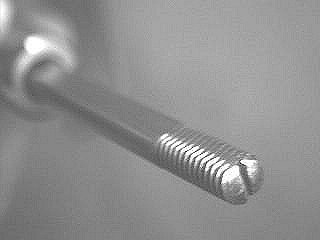
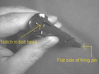
| Step
2 - Orient the firing pin |
| Notice
that the firing pin shaft has a flat slide. Orient the flat side
of the firing pin so it is facing the same direction as the notch in the
bolt head. |
Flat side
of firing pin shaft.
|
|
Firing
pin oriented for assembly.
|
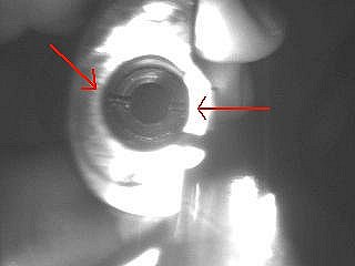
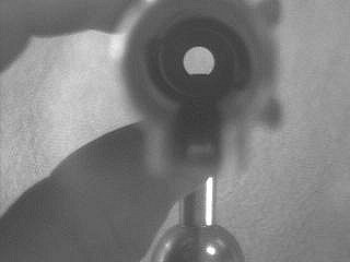
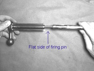
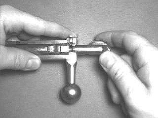
| Step
3 - Install bolt head into bolt body |
Note:
Hold the safety lever in the "safe" position during this procedure.
With the flat side of the
firing pin shaft aligned towards the bolt handle, insert the head assembly
into the bolt body. If everything is aligned just right, the
bolt head will smoothly slide into the body, rotating counter-clockwise
as it goes in. If it doesn't completely slide into the bolt body,
follow the directions below. |
Hole that
firing pin shaft passes through.
|
|
Insert
the bolt head into the bolt body as shown.
|
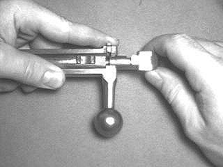
If it
goes in about this far and then stops...
|
|
...push
in and turn clockwise. In about 1/3 revolution it should slide in
a bit like this.
|
Now, keep
pushing in and turn it counter-clockwise. In about 1/2 revolution
it should slide into the bolt body.
|
|
When the
bolt head is fully seated and properly aligned, it will look like this.
Notice that the notch in the head faces away from the bolt handle.
|
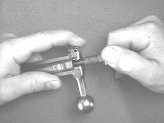
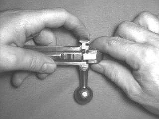
| Step
4 - Install the extractor |
| With
the bolt head extended to the position shown below, put the extractor into
it's slot and push it into place. Rotate the bolt head counter-clockwise
while simultaneously pushing it into the bolt body, until it "clicks" into
place. Keep the safety lever in the "safe" position during this procedure. |
Putting
the extractor into its slot.
|
|
Pushing
the extractor into place. Bolt head is extended about 1 inch.
Notice that slot in bolt head is
almost lined up with the extractor
slot.
|
Rotating
the bolt head counter-clockwise until it "clicks."
|
|
Thumb
holding safety lever in "safe" position.
|
| Step
5 - Seat the bolt head |
| Now
give the bolt head a rap with a soft faced hammer and rotate it into the
retracted position. |
Rap on
the bolt head ...
|
|
... until
it turns counter-clockwise and seats.
|
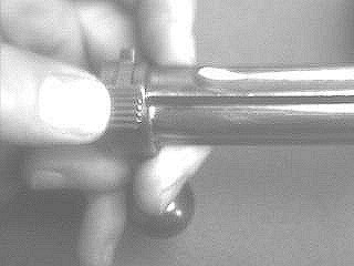
| Step
6 - Install the cocking piece |
| Hold
the safety lever at the halfway position and screw the cocking piece onto
the firing pin shaft until it touches the bolt body. Now pull the
cocking piece back and move the safety lever into the "safe" position.
Let the cocking piece move inward under spring pressure. Holding
the safety lever in the "safe" position, screw the cocking piece onto the
rear of the firing pin shaft. If it's tab doesn't line up the the
notch in the bolt body when fully tightened, just unscrew it a 1/3 turn
or so until it does. Pull the cocking piece back and move the safety
lever to it's halfway position. Let the cocking piece move inward. |
Hold the
safety lever at the halfway position...
|
|
...and
screw the cocking piece onto the firing pin until it touches the bolt body.
|
Now pull
the cocking piece back and move the safety lever to the "safe" position.
|
|
Let the
cocking piece retract inward while holding the safety lever at the "safe"
position.
|
Screw
the cocking piece fully on. If it doesn't line up properly...
|
|
...unscrew
it about 1/3 turn until the cocking piece tab line up with the notch in
the bolt body.
|
Now put
the safety lever at the halfway position and let the cocking piece move
inward.
|
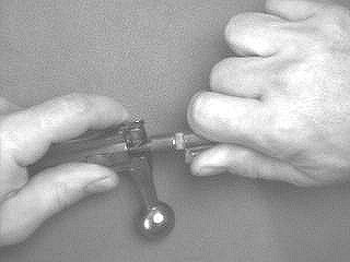
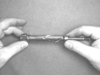
| Step
7 - Extend the bolt head |
| NOTE:
Wipe any oil off the bolt so you can get a good grip on it. The
bolt head must be in the extended position for installation in the rifle.
I find it easiest to accomplish this by holding the bolt in my left hand
and pressing against the extractor with my thumb. Then I grab the
bolt head with my right hand and pull it outward while turning it clockwise
simultaneously until it "clicks" into place and locks.
The trick is
to push with your left thumb and pull with your right hand
at
the same time.
The bolt may now be installed
in the rifle. |
Holding
bolt in left hand with thumb on extractor
|
|
Pull &
rotate bolt head clockwise until it "clicks" into place.
|
CONCLUSION
The Mannlicher
Model 95 straight pull rifle served admirably for almost fifty years, and
saw service in two world wars as well as a number of post-war "wars of
national liberation." It was a reliable, accurate and hard hitting
rifle that was well liked by the troops who carried it. Moreover,
it boasted one of the fastest actions ever devised for a manually operated
rifle. Despite this, the design fell by the historical wayside, overshadowed
by they wildly more popular (and more marketed) Mauser design. However,
it's interesting to speculate as to how successful the design might have
become had the Hapsburg empire survived the First World War. One
only has to look to the Swiss use of the Schmidt-Rubin as an example of
the longevity of the straight pull rifles.
Current availability
of the carbine and short rifle variants of the M95 is quite good, with
prices that are very reasonable. Infantry long rifles are available,
but are somewhat harder to find and command slightly higher prices.
Ammunition is also available, and can occasionally be found for as little
as eight cents per round in volume.
BIBLIOGRAPHY
Smith, Walter
H.B., Mannlicher Rifles and Pistols, (Military Service Publishing
Company, Harrisburg, Pennsylvania: 1947)
Mannlicher
Rifles and Pistols is an out of print volume. You can search
for it on any of many out of print search engines on the 'Net.
HOME