| Kicking
the Kick: The Inventions of
Richard Cutts |
 |
|
|
|
|
Firearms Technical Trivia, May 2001:
| Kicking
the Kick: The Inventions of
Richard Cutts |
 |
Recoil control has long been a concern for designers of both military and commercial firearms in the United States. Indeed, a tour through the museum at the Springfield Armory National Historic Site would lead one to believe that legions of inventors had been trying from time immemorial to solve the recoil problem. To this day, muzzle recoil reduction devices work on the same principles as the early devices. Specifically, the devices arrested a portion of the muzzle blast after it left the muzzle and turned it sideways or backward. Since approximately a quarter of the recoil velocity of a high powered rifle is caused by the thrust of the jet of propellant gases as they exit the muzzle at high speeds. If this thrust could be entirely arrested, the recoil velocity of the rifle would be cut by about a fourth. Since recoil energy is is proportional to the square of recoil velocity, anything that reduces the energy by one-fourth will reduce the energy by approximately 44%.
It's not especially realistic to expect to trap all the exiting gas; a hole has to be left for the bullet to exit through, and a large part of the gas will follow the bullet out at high velocity. However, the portion of the gas that is trapped can not only be stopped from giving the gun a rearward impetus, but can also be used to impart a forward thrust on the gun, thus further reducing perceived recoil. This can be done by shaping the vanes or ports of the muzzle device so that they turn the escaping gases toward the rear. The principle is like that of the ideal turbine - if the ports on the brake are properly shaped, they could supposedly absorb twice the momentum of the gases they trap. First, they could extract momentum by bringing gases to a stop, and then extract an evil amount of momentum by giving the gases a push to the rear. No device is this efficient in practice.
Many brakes were tested, but none adopted, as all of them created an intensified muzzle blast to the side of the shooter.
RICHARD
CUTTS
Soon after the end of the end of
World War One, a Marine colonel named Richard Cutts paid a visit to Springfield
Armory. He brought with him a muzzle brake which he had entitled
the "Cutts Compensator." Cutts' compensator used radial slots to
counteract recoil, but the principles behind his efforts were much more
complex than indicated by the compensator's simple construction.
An analysis of several of Richard Cutts' patents provides great insight
into the engineering principles behind his recoil reduction devices in
particular and muzzle brakes in general.
US Patent No. 1,605,393 November 2, 1926: Climb Arrester
 |
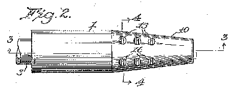
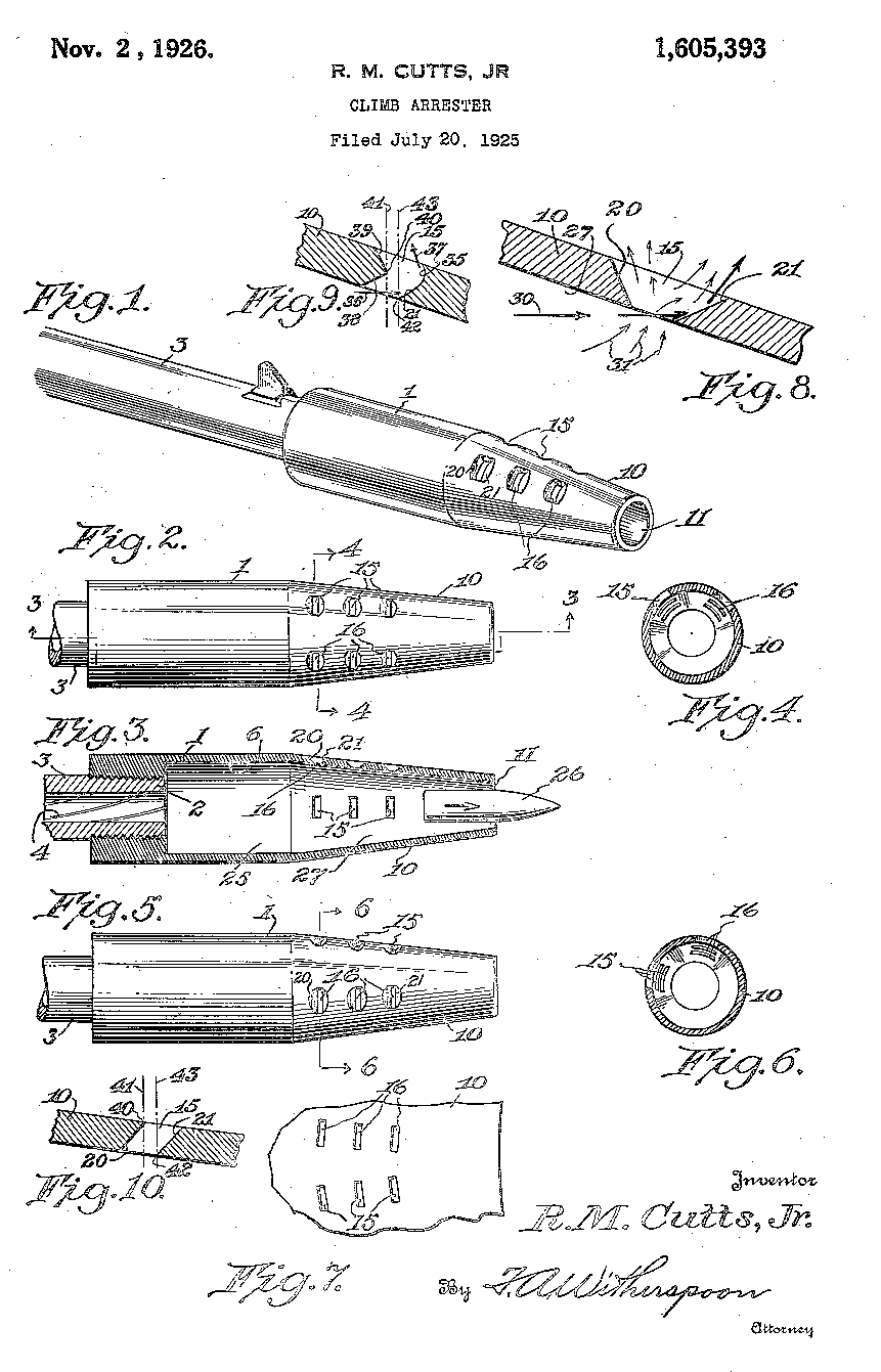
Cutts' patent number 1,605,393 was granted on November 2, 1926 and covered what he referred to as a "climb arrester." It was intended to prevent the "climb, jump or whip, as well as reduce the recoil of machine guns, automatic and semiautomatic rifles." The operation of the device covered by this patent was a function of both its shape and the apertures arranged along the long axis. As can be seen from the patent drawings, the forward portion of the device tapers to an opening that is slightly larger than the diameter of the bullet for which the firearm is chambered.
The device is constructed so as to form an expansion chamber that extends from the muzzle to the device's exit aperture. After the bullet exits the muzzle, the propellant gases enter the expansion chamber at high speed and expand first into the cylindrical portion of the the device and then into the tapered portion. As the gas continues to expand, its exit at the forward end of the device is blocked by the bullet's presence in the opening. For a brief moment, the gas pressure impinges against the tapering walls of the device, creating a forward thrust that mitigates the rearward thrust of the recoil.
Additionally, some of the high pressure gas escapes through the ports in the tapered portion of the device. This route forces the gas to exit the system at right angles to its original direction of thrust. By forcing the gas to escape upward, a downward thrust is imparted to the muzzle of the device, compensating for the tendency of the firearm to climb when fired. Additionally, the pressure of the escaping gases as they move against the beveled surfaces of the ports will also act on the firearm so as to provide a forward and downward motion.
US Patent No. 1,636,357 July 19, 1927 Anticlimb Device
 |
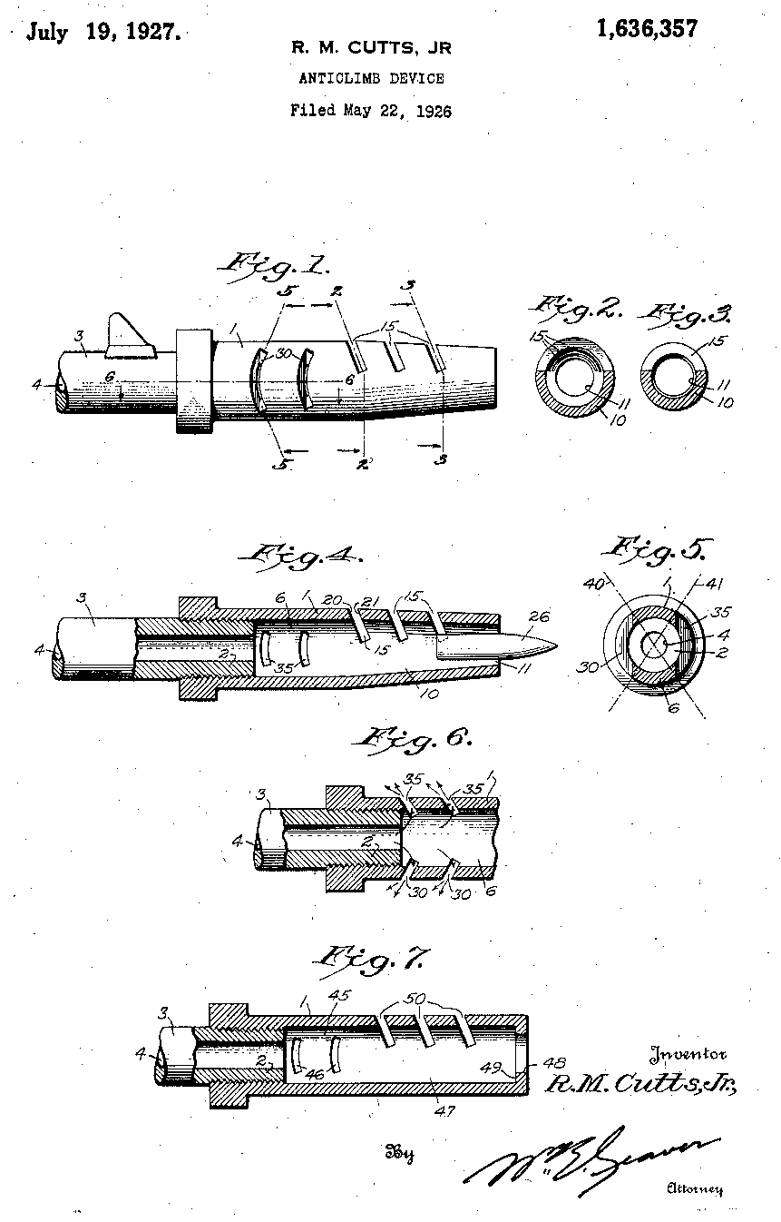
Cutts' patent number 1,636,357 was granted on July 19, 1927 and covered what he referred to as an "anticlimb device." It was intended to serve as an improvement to Cutts' earlier patent that would both be more effective and less expensive to produce. It consists of a cylinder, threaded at one end so as to accept the firearm's muzzle, which provides an expansion chamber. At the approximate center, the cylinder is tapered to provide a compression chamber. The opening at the far end is slightly larger than the caliber of the ammunition for which the firearm is chambered. There are a series of inclined apertures or slots cut in the sides of the cylinder, and another set on top of the cylinder that is above the centerline of the cylinder, and set at an angle to the vertical. Additionally, there are a series of inclined slots cut into the sides of the cylinder.
After the bullet leaves the muzzle, it is followed into the expansion chamber by the propellant gases. When the bullet reaches the exit hole, it provides a temporary blockage, and the pressure of the propellant gases behind it increases. The slots provide a means of gas escape, but in doing so, they force the gas to escape at right angles to the original direction of travel. The gases escaping through the slots on the side of the cylinder provide forward thrust on the device, counteracting the rearward recoil thrust. As the upper slots are arranged above the horizontal center of the cylinder, the gases escaping through them provide a thrust that acts on the cylinder's lower wall, counteracting the muzzle's tendency to rise under recoil forces.
US Patent No. 1,773,260 August 19, 1930 Compensator Device
|
|
It has been found by analysis and research that the vibrations of a gun barrel will cause the bullet to depart from the axial direction established by the bore when the gun is at rest. The two most important of these vibrations are the fundamental and the first overtone, which will cause the barrel to be actually bend in an undetermined direction at the time of the emission of the bullet, and which usually work in algebraic combination, causing what is known as the bend error.In essence, Cutts identified two key causes of shot dispersion errors: Barrel whip, and gas pressure within the shot column. To overcome these problems, the Cutts patent uses a two piece device. The first piece is a slotted expansion chamber threaded directly on to the barrel. The second is a conical device threaded onto the expansion chamber serving a multipurpose role as compression/recompression chamber and choke tube. As the shot exits the barrel, it is followed by the propellant gases. When the shot column arrives at the rear edge of the compression chamber it begins to bunch up and obturate the bore, providing a temporary seal. The pressure of the propellant gases behind the shot column increases. The slots provide a means of gas escape, but in doing so, they force the gas to escape at right angles to the original direction of travel. The gas escaping through the slots on the side of the expansion chamber not only compensates for barrel whip, but also removes the majority of the gas within the shot column. As a result, when the shot leaves the forward portion of the compensator, it is substantially free from the influence of barrel whip, and the only force acting on the dispersion pattern is that of the choke.The muzzle while traveling from one limit of the vibration to the other limit has a definite lateral velocity which is greatest halfway between the limits of the vibration so that if the bullet emerges at a period of the vibration between the limits thereof, said bullet will have a definite lateral velocity in addition to its forward velocity. This is known as the swing error and the combination, of the bend and swing errors causes the bullet to strike to one side, above, or below the desired point of impact. This actual point of hit will vary according to conditions of powder charge as well as other known conditions, all of which cause alterations in the amplitude and frequency of the vibrations, but the bullet being a solid is affected as a whole. Greater accuracy has been shown on the range by the use of the above mentioned patented compensator on solid projectiles due, to the dampening to a great extent of both the frequency and amplitude of these vibrations.
The check of the kinetic energy of the gas in the compensator, caused by the compression chamber and the almost closure of the compensator exit by the bullet, causes a reaction of this kinetic energy against the following gas column, resulting in a heavy increase in pressure in the compensator compression chamber. This increase in pressure has been shown on the chronograph to definitely increase the velocity of the projectiles of small arms or field guns over the velocity it had on its departure from the gun's muzzle. The above is necessary explanation to elaborate the claims of this improvement of the compensator for shotguns, and guns in which the projectile is not a unit mass.
The vibration of a shotgun barrel , owing to its form and structure, is much greater go than that of a barrel of a rifle or field gun, and is infinitely more variable owing to the various charges of shot and powder used. It has always been a difficult matter to maintain the shot group in the densities desired for the various ranges, and to control these densities, since outside influences such as wind, air resistance, etc. are common to all.
The shot column in a shotgun, ballistically speaking, is traveling at a comparatively slow velocity and, as it emerges from the usual gun barrel is subjected to the bend and swing errors. However, as the shot column is not a solid it does not respond as a mass, with the result that different sections of the shot column are subjected to different angular departures caused by the bend error. Further, different and separate parts of the same column are given different and separate lateral velocities caused by the swing error.
Further, it has been established by photographic means that the leakage of gas beyond the powder wads establishes a high gas pressure in the interstices of the shot column, during its progress through the barrel. On reaching the muzzle, this gas is no longer confined by the barrel walls and expands laterally from within the shot column, imparting lateral velocities particularly to the outer layers shot, which materially add to the dispersion of said shot, with resultant undesirable shot patterns. The effect, therefore, is a too great opening out of the pattern which is viciously increased when the heavier long range loads increase not only the vibration both as to amplitude and frequency but the gas pressure within the barrel and shot column. It thus results that when a decreased pattern area is desired, a hollow pattern of large area is secured instead. The compensator when applied to a shotgun will dampen the vibrations referred to and thus diminish the effects of these errors, but the bend and swing still have effects on the shot dispersion.
A further cause of undesired shot expansion, has been shown, photographically, to lie ill the powder wads driving the shot column from the rear under pressure of the following gases, after the shot column has left the barrel and is no longer supported by the barrel walls, the effect being to expand the base of the said column, and this expansion is assisted by the beforementioned interior gases, with resultant and considerable lateral velocities to the part of the column so affected. The compensator when applied to the shotgun will remove this error, and by releasing the pressure from behind the powder wads before the wads have cleared the compensator muzzle, will prevent any further action of this nature.
CONCLUSION
Richard Cutts, though largely unknown
today, was the pioneer in the field of compensated firearms. His
compensators were relatively common through the 1930's, 1940's, and 1950's,
being fitted regularly to Winchester, Browning, Remington, and Ithaca
shotguns, and also to military Thompson submachineguns. While the
use of Cutts compensators is rare today, the principles covered in his
many patents can be found a a great number of modern firearms. Specifically,
the compensated pistols favored by competitors make use of many of Cutts'
ideas. Indeed, it would be a rare compensator design that didn't
take advantage in one form or another of an idea originated by Richard
Cutts.
Note: Data for this month's trivia page was gathered from:
The United
States Patent and Trademark Office. Comprehensive patent research
can be conducted online at the Patent and Trademark website, http://www.uspto.gov.