CRUFFLER.COM
presents
HISTORIC
FIREARM OF THE MONTH,
May
2000:
 |
 |
|
 |
Type:
Air Cooled General Purpose Machinegun
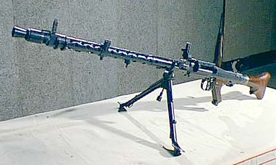
System of Operation: Short Recoil of Barrel, selective fire Caliber: 7.92x57mm (7.92mm Mauser) Capacity: Belt feed system Sights: Blade front, v-notch rear, optical sight used with heavy machine gun mount Length: 48" Weight (unloaded): 27 lbs Barrel: 24.6" |
At the beginning of the Second World War, the German Army (Wehrmacht) was equipped with large numbers of a modern standard machine gun, as well as significant numbers of older types for second echelon formations. The Wehrmacht believed this weapon, the Maschinengewehr 34 (MG 34) to be the best of its class in the world. While the MG 34 proved to be successful in combat, it also proved to have several important deficiencies, and by the end of the Second World War it was considered to be superseded, and would have been withdrawn from service had its replacement been available in sufficient quantities.
The MG 34 was developed in the early 1930's as a general purpose machinegun in response to a set of Wehrmacht requirements. It was also proposed to the Luftwaffe as an aircraft machine gun. At the time, the Luftwaffe determined that the new machinegun was not suitable for replacing the aircraft weaponry then in service. Interestingly, during the latter part of the Second World War, the Luftwaffe did publish a manual for the MG 34, which was then being used as a ground defense weapon at air force installations as well as by the Fallschirmjager, the German Paratroops (who were officially Luftwaffe troops). The German Navy, the Kriegsmarine, also used the MG 34. While production of the MG 34 came to an end in 1945, it continued in service in Portugal, where it is known as the Metralhadora m/945, as well as in several other nations.
The MG 34, like many German designs of the Second World War, had its roots in the First World War. Based on the experiences of the First World War, the Wehrmacht wanted an Einheitsmaschinengewehr - a universal or general purpose machinegun. A single machinegun was envisioned, one that would be adaptable to various missions by using a variety of mounts and accessories. Having a single machinegun would simplify production, maintenance, and training. Also, a gun with a quick change, air cooled barrel was specified. At the time the requirements were specified, both Mauser and Rheinmetall had air cooled machineguns in development, but these were primarily light machineguns without the additional features needed in a general purpose machinegun. These requirements and development efforts were not happening in a vacuum. History was turning up the pressure - Germany was beginning to rearm in defiance of the Treaty of Versailles, and the Wehrmacht wanted a modern machinegun.
The Wehrmacht's Ordnance Department (Heereswaffenamt) examined both the Mauser and the Rheinmetall guns closely. Both had certain excellent features, but neither included all the features that were deemed necessary. As a result, it was decided that an entirely new gun was needed. Rheinmetall was selected to develop the new gun, and the design team was headed by Louis Stange. The Heereswaffenamt project officer for the new gun was Major Ritter von Weber. Later, the Wehrmacht made arrangements to compensate Mauser for the use of certain patented features used in the new machinegun.
MG 34: SYSTEM ORIGINS
The results of Stange's and von Weber's efforts was, arguably the most elaborate machinegun system ever produced. The primary components of the system consist of the machinegun itself, the mount for the heavy machinegun role, the optical sight to be used on the mount, the lightweight tripod used for the antiaircraft role, and an accessory set. The MG 34 had an integral bipod. There are over one hundred individual manufactured components in the gun itself, and when the components for all elements of the system are totaled the number of individual parts becomes truly excessive. As an example, the heavy machinegun mount, the Lafette 34 has more than 200 individual components. That such a complex machinegun system was developed in the 1930's can be explained by Wehrmacht doctrine of the period, which classified the machinegun as the most important weapon in the infantry arsenal. The true design flaw was not in the gun itself, but rather with the design paradigm that failed to stress simplicity as a key component.
This can be further understood as the development took place when Germany was a peace, and was stepping up its rearmament program. There were, at the time, no pressing shortages of materials, labor, or facilities or funds. As a result, the Rheinmetall designers came up with a handsome looking machinegun with a number of innovations thought to be desirable in a general purpose machinegun. It is almost as if the excellent finish and almost over-engineered construction of the new gun were intended to impress the observer. The Wehrmacht of the 1930's was dominated by officers who had served in the First World War, and the dominant tactical reality for these men was that the machinegun would remain the principal infantry weapon in any future conflict. They wanted an impressive machinegun in a hurry. Little thought seems to have been given to the issues involved in producing such a finely made, complex system during wartime.
The MG 34 was a sum of many parts, and this can be better understood by tracing its features back to earlier guns. The bolt came from the Mauser prototype light machinegun of 1932. The bipod was derived from the Rheinmetall MG 13. The concept of making the trigger serve as the fire selector switch also came from the MG 13. The double drum magazine was already in use with the MG 15. The accelerator was adapted from the Soda machinegun which was developed by Louis Stange at Sommerda. The mount for the heavy machinegun role was developed from the Solothurn mount number 57-300. Also included in developmental guns was a mechanism to allow for high and low rates (700 and 1,000 rpm) of automatic fire. This feature was not included in production guns.
Once the gun was placed into serial production, several contractors were assigned the work of producing the guns. These contractors included:
| MG
34: SYSTEM OPERATION
As issued, the MG 34 had a cyclic rate of about 900 rounds per minute, but this varied from gun to gun. It also varied depending on the method of ammunition feed - belt feed was slower than using the double drum magazine, which fed cartridges under spring tension. Based on operational experience, an increase in the rate of fire was requested. Indeed, German studies had shown that burst dispersion could be minimized in light machineguns by increasing the cyclic rate. In order to increase the cyclic rate and simplify the machinegun a complete |
As an interesting historical footnote, there seems to be no reason to believe that the development of the MG 34 represented an attempt to evade the Treaty of Versailles. The German concept of a general purpose machinegun dated from the First World War. The fact that the same gun was to serve as the light machinegun on a bipod and as the heavy machinegun on the proper mount was not related to the treaty, which was written in very general terms. Specific enforcement of the treaty was accomplished by control commissions appointed by the victorious Allies, with each commission dealing with specific treaty clauses. While these control commissions were very active for a few years after the war, their membership dwindled in the late 1920's. Long before Germany renounced the treaty, there were no foreign officers in Germany to enforce it. It is important to remember that the treaty never attempted to define classes of weapons, such as light and heavy machineguns. This was a function of the control commissions. Since the commissions had left Germany before the development of the MG 34 began, the treaty had no effect on the gun's development. |
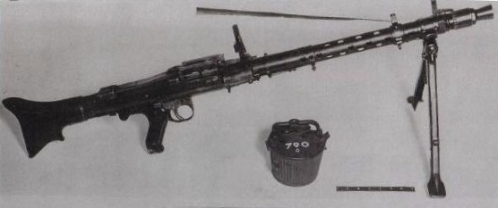
MG 34/41 Image Credit: Musgrave, Daniel D., German Machineguns, Ironside International Publishers (Alexandria, Virginia 1992) Page 295 |
As part of the MG 34/41 development, modifications were made to all the MG 34's major assemblies, and the two guns lacked interchangeability of parts. The differences were as follows: The MG 34/41 had a shorter barrel, the bolt head locked to the barrel via lugs instead of interrupted threads, |
The MG 34 is operated by short recoil of the barrel, assisted by a recoil booster at the muzzle. Upon firing, the barrel recoils for a distance of approximately 3/4", after which it returns to the forward position under the influence of the barrel return spring. When the barrel is forward, the bolt head is locked to the rear of the barrel. The unlocking process begins when the barrel begins to move to the rear and is completed just before the barrel recoil is arrested by the barrel buffer.
There is a short locking collar at the rear of the barrel. A portion of the collar, behind the rear face of the barrel has interrupted buttress threads on the interior. On the exterior of the collar are two large lugs that enter into and travel in the appropriate slots in the barrel jacket so as to prevent rotation of the barrel. Extending to the rear from the collar are a pair of cams. These cams have two functions: To cause the locking of the bolt head and to accelerate the bolt after unlocking.
The barrel assembly (barrel and collar) is symmetrical about the long axis. The lugs, cams, and buttress threads are arranged in pairs so that the barrel cannot be installed incorrectly. The barrel can be installed in either of two ways as the lugs are 180 degrees apart.
The bolt assembly consists of two sub-assemblies, the bolt head and the bolt body. The bolt body carries the bolt head with it and reciprocates within the receiver. The bolt head travels with the bolt body but is also capable of a degree of rotation about an axis coinciding with that of the bore. The bolt body is a relatively simple affair. It has guides on both the right and left sides. As the body moves back and forth in the receiver, these guides ride in tracks within the receiver walls. On the bottom of the bolt body is a lug that engages with the gun's sear. On the top of the body are a pair of studs that drive the belt feed mechanism. The rear face of the bolt body provides a surface against which the thrust of the mainspring is exerted, and a surface to contact the buffer during recoil. The bolt body is bored through from front to rear so as to accommodate the rear portion of the bolt head, and to allow the bolt head to rotate with respect to the bolt body. The body also has cam surfaces for cocking and releasing the firing pin, which is carried in the bolt head. The bolt assembly as a whole can be pulled to the rear by the action of the cocking handle.
The bolt head is the piece that locks the breech of the machinegun and supports the base of the cartridge during firing. It is generally cylindrical in shape, and near the forward end has interrupted buttress threads that engage with those on the interior of the barrel locking collar during firing. Locking and unlocking are accomplished by rotation of the bolt head relative to the collar. This rotation is caused by two pairs of rollers mounted on two laterally extending studs on the bolt head. The two rollers on each stud are capable of independent rotation. The inner pair of rollers serve to lock the bolt head by rolling against locking cams on the rear of the barrel collar, and thus rotating the bolt head into the locked position. The outer pair of rollers serve to unlock the bolt head during barrel recoil. The rollers bear against fixed cam surfaces in the receiver, thus rotating the bolt head into the unlocked position. The rollers themselves are not locks - they merely act on the locking device, the bolt head, and do not resist the force of cartridge ignition.
The front face of the bolt head is countersunk so as to receive the case head. The extractor, which is spring loaded, is on the bottom of the head, while the ejector, which is free floated, is retained in a hole at the top of the head. The ejector contacts a hardened stop in the receiver during firing. Protruding slightly above the top of the bolt head is a spring loaded member that contacts the base of each fresh cartridge, feeding it into the chamber during the forward travel of the bolt assembly.
As mentioned previously, the bolt head also houses the firing pin and spring. The firing pin is placed into the cocked position during the unlocking of the bolt head and is retained in the cocked position by a pivoting lever on the right side of the bolt head. Once locking is completed, the tail of the lever comes into contact with an inclined surface on the bolt body and moves so as to release the firing pin.
After firing, the bolt assembly is accelerated to the rear by an interaction between the bolt head rollers and the cams on the barrel collar and in the receiver. As recoil begins, the outer pair of rollers on the bolt head contacts the fixed cams on the receiver, and the bolt head is violently rotated so as to disengsage the buttress thread and unlock. During this rotation, the inner pair of rollers rolls around the cams on the rear of the barrel collar. These cams are shaped so as to ensure that the bolt head receives a violent thrust away from the barrel locking collar towards the rear of the receiver.
The MG 34 was normally belt fed. A partly curved feed lever is located in the hinged receiver cover. The feed lever has a rib on the bottom that engages the two feed studs on the top of the bolt body. As the bolt reciprocates, it causes the feed lever to oscillate, moving the belt feeding pawl. The belt moves during the rearward travel of the bolt assembly. During the forward motion of the bolt, a pair of belt holding pawls prevents the belt from slipping back. Cartridges are forced down into the feed opening in the cartridge feed block by spring loaded cartridge feed guides. Cartridges were normally fed from left to right. This is reversible using a special right handed feed lever and the repositioning of the other components of the feed assembly. This right handed feed capability was provided for use in fortifications, vehicles, and other installations where a space limitation might prevent left-handed feed.
The MG 34 was originally designed to use a 75 round double drum magazine called the Patronentrommel 34 (cartridge drum 34). When this drum was used, the belt feed cover and the cartridge feed block were removed from the gun and a special receiver cover was installed. The Patronentrommel 34 was officially discarded between 1939 and 1940. The replacement for the Patronentrommel 34 was the Gurttrommel 34 (belt drum 34). The belt drum as a simple sheet metal container holding a fifty round belt section. The drum mounts using a hook and latch that engage with projections on the feed block. The Gruttommel 34 was capable of left hand feed only.
The pistol grip is secured to the receiver by two pins. It houses the trigger, sear, and safety mechanisms. The choice of semiautomatic or full automatic fire depends on whether the upper or the lower portion of the trigger is pressed. The upper part is marked E for Einzelfeuer (single fire), and provides semiautomatic fire. The lower is marked D for Dauerfeuer (continuous fire) and provides fully automatic fire. The safety is a pivoting lever on the right side of the pistol grip just above the trigger. In the forward position the safety is off and the letter F for "feuer" (fire) is exposed, and when pivoted to the rear, the F is covered, and the letter S for "sicher" (safe) is exposed.
The ejection port is under the receiver and has a hinged, spring loaded dust cover. When in the closed position, the dust cover opens automatically when the trigger is pressed.
The muzzle attachment is a combination flash suppressor and recoil booster, and consists of three parts: The flash suppressor, the gas nozzle, and the front barrel bearing. The bearing has external threads that engage threads within the front of the barrel jacket. The bearing also has external threads to which the flash suppressor attaches. The gas nozzle is inside the rear cylindrical portion of the flash suppressor. It has a conical passage for the bullet with the large end of the cone facing the muzzle.
| One of the most important features of the MG 34 is its quick change barrel. Barrels were normally changed after about 250 rounds of rapid fire. With the gun on the bipod, the bolt was moved to the rearmost position, and the gun was placed on safe. The receiver latch below the rear sight was depressed and the receiver was rotated to the left, exposing the rear of the barrel. The muzzle was raised, and the hot barrel slid out to the rear. Another barrel was | 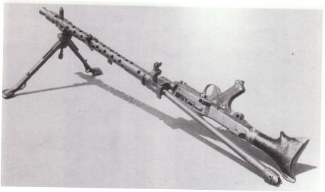
Barrel Change Image Credit: Musgrave, Daniel D., German Machineguns, Ironside International Publishers (Alexandria, Virginia 1992) Page 293 |
MG 34: EPILOGUE
The MG
34 was one of the best known weapons of the Second World War and is a highly
prized collector's item today. For all its overcomplexity, the gun
presented a large number of innovative concepts and ideas that are still
considered "standards" in automatic weapons design to this day. Nevertheless,
there are some important "negative" lessons to be learned from the MG 34.
Paramount among them was the importance of stressing both simplicity and
ease of manufacture during the design phase of any small arms project.
It is interesting to note that the United States has seemingly forgotten
this lesson in the search for the Objective Individual Combat Weapon (OICW).
We can only hope that the lessons taught to the Wehrmacht by the
MG 34's complexity and difficulty of manufacture will not have to be learned
anew about the OICW during war.
BIBLIOGRAPHY
Ezell, Edward, C., Small Arms of the World, 12th Edition, (Stackpole Books, Harrisburg, Pennsylvania: 1983)
Musgrave, Daniel D., German Machineguns, (Ironside International Publishers, Alexandria, Virginia: 1992)
German
Machineguns is available from IDSA Books. Click on the
image to order:
Small
Arms of the World, 12th Edition is available from IDSA Books.
Click on the image to order: